The C0, CG, and C1 series cameras with global shutter CMOS sensors were designed to be small, lightweight imagers for Moon and planets and for automatic telescope guiding. With proper image calibration, these cameras provide surprisingly good results also in entry-level deep-sky imaging.
The used CMOS sensors response to light is linear up to very close to saturation point. So, the C0, CG, and C1 cameras can be used for some entry-level scientific applications for instance in the variable star research etc.
Greater dimensions of the C1 models allowed adding of some features, not available on the C0 cameras, like cooling fan and mounting threaded holes.
The C0, CG, and C1 cameras are designed to work in cooperation with a host Personal Computer (PC). As opposite to digital still cameras, which are operated independently on the computer, the scientific cameras usually require computer for operation control, image download, processing and storage etc. To operate the camera, you need a computer which is compatible with a PC standard and runs modern 32 or 64-bit Windows or Linux operating system.
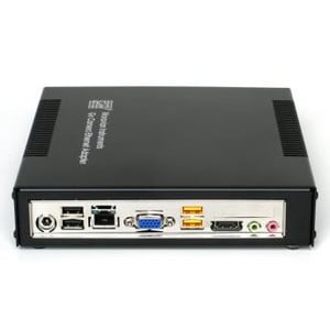
Cameras are designed to be connected with the host PC through USB 3.0 interface, operating at 5 Gbps. Cameras are also compatible with USB 2.0 port to communicate with a host PC. Alternatively, it is possible to use the Moravian Camera Ethernet Adapter device. This device can connect up to four Cx (with CMOS sensors) or Gx (with CCD sensors) cameras of any type and offers 1 Gbps and 10/100 Mbps Ethernet interface for direct connection to the host PC. Because the PC then uses TCP/IP protocol to communicate with the cameras, it is possible to insert WiFi adapter or other networking device to the communication path.
The C0, CG, and C1 cameras do not need an external power supply to operate, they are powered through the USB connection from the host PC. Sensors used in C0, CG, and C1 cameras offer programmable gain from 0 to 24 dB, which translates to the output signal multiplication from 1× to 15.9×. Gain can be set with 0.1 dB step.
C0, CG, and C1 cameras are capable of very short exposures. The shortest exposure time is 125 μs (1/8000 of second). This is also the step, by which the exposure time is expressed. So, the second shortest exposure is 250 μs etc.Long exposure timing is controlled by the host PC and there is no upper limit on exposure time. In reality the longest exposures are limited by saturation of the sensor either by incoming light or by dark current
Cooling: Dark current is an inherent feature of all silicone circuits. It is called “dark”, because it is generated regardless if the sensor is exposed to light or not. Dark current, injected into individual pixels, appear in image as noise. The longer exposure, the greater amount of noise is present in every image. As it is generated by random movement of particles, it depends on the temperature exponentially (this is why the noise generated by dark current is also denoted “thermal noise”). Typically, lowering the sensor temperature by 6° or 7 °C halves the dark current.
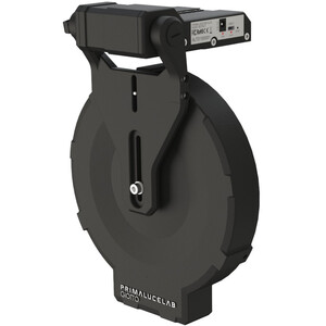
While none of the C0, CG, or C1 cameras are equipped with active thermo-electric (Peltier) cooling, the C1 models employ a small fan, exchanging air inside the camera body. What is more, a small heat sink is located directly on the sensor to remove as much heat as possible (with the exception of C1-1500, which sensor is too small to be equipped with a heat sink). So, the C1 sensor cannot be cooled below the ambient temperature, but its temperature is kept as close to environment as possible. Compared to closed designs of the C0 and CG cameras, the sensor temperature in the C1 can be between 7° and 10°C lower and resulting dark current may be less than a half.
The fan operation can be controlled from the software.
Autoguider port: A lot of astronomical telescope mounts (especially the mass-manufactured ones) are not precise enough to keep the star images perfectly round during long exposures without small corrections. Cooled astronomical cameras and digital SLR cameras allow perfectly sharp and high-resolution images, so even a small irregularity in mount tracking appears as star image deformations. C0, CG, and C1 cameras were designed especially with automatic mount guiding on mind.The guiding cameras were designed to operate without any mechanically moving parts (with the exception of magnetically levitating fan). Electronic shutter allows extremely short exposures and also obtaining thousands of images in a short time, which is necessary for quality guiding.
The C0, CG, and C1 cameras work in connection with a host computer (PC). Guiding corrections are not calculated in the camera itself, it only sends acquired images to the PC. The software running on the PC calculates the difference from required state and sends appropriate corrections to the telescope mount. The plus side of using a PC to process images is the fact, that current PCs provide overwhelming computational power compared to any embedded processor inside the guiding camera. Guiding algorithms then can determine star position with sub-pixel precision, can match multiple stars to calculate average difference, which limits the effects of seeing, etc.
Calculated corrections can be sent back to mount using PC-to-mount link. If the mount controller does not support so-called “Pulse Guide” commands, it is possible to use “Autoguider” port. It is enough to connect the camera and the mount using standard 6-wire cable and guide the mount through the camera. The maximum sinking current of each pin of the C0, CG, and C1 camera is 400 mA. If the mount does not treat the autoguider port as logical input only, but switches the guiding motors directly by these signals, a relay box must be inserted between the camera and the mount. The relay box ensures switching of currents required by the mount.
Powerful SIPS (Scientific Image Processing System) software, supplied with the camera, allows complete camera control (exposures, cooling, filter selection etc.). Also automatic sequences of images with different filters, different binning etc. are supported. With full ASCOM standard support, SIPS can be also used to control other observatory equipment. Specifically the telescope mounts, but also other devices (focusers, dome or roof controllers, GPS receivers etc.).
SIPS also supports automatic guiding, including image dithering. Both “autoguider” port hardware interface (6-wire cable) and mount “Pulse-Guide API” guiding methods are supported. For hi-quality mounts, capable to track without the necessity to guide at last during one exposure, inter-image guiding using the main camera only is available.
But SIPS is capable to do much more than just camera and observatory control. Many tools for image calibration, 16 and 32 bit FITS file handling, image set processing (e.g. median combine), image transformation, image export etc. are available.
As the first “S” in the abbreviation SIPS means Scientific, the software supports astrometric image reduction as well as photometric processing of image series.
The “Guiding” tool allows switching of autoguiding on and off, starting of the automatic calibration procedure and recalculation of autoguiding parameters when the telescope changes declination without the necessity of new calibration. Also swapping of the German Equatorial mount no longer requires new autoguider calibration. There is also a graph showing time history of guide star offsets from reference position in both axes. The length of graph history as well as the graph range can be freely defined, so the graph can be adjusted according to particular mount errors and periodic error period length. Complete log of calibration procedure, detected offsets, correction pulses etc. is also shown in this tool. The log can by anytime saved to log file.